Last week’s guest on the podcast was Sam Newman, who had released a book I’ve personally long awaited titled ** Building Resilient Distributed Systems**. It’s an especially timely book for many of us software engineers, as we’re seeing more outages with nearly all services and systems – much of it caused by more code deploys thanks to AI agents writing more code; and more bugs causing more incidents in production.
Sam’s book being “fresh out of the oven,” it naturally also touches on what AI changes as we design resilient systems. In fact, Sam told me that he took a total of three years to finishe the book – instead of the two he originally planned – because he went back and reworked all parts of the book, updating parts where AI is relevant to talk about.
I asked Sam if he would consider sharing an excerpt from the book, with sections especially relevant for anyone building systems that ought to be reliable. Sam graciously agreed, and today’s issue covers a few important topics, spread across two chapters from his book. We get into:
**Disaster recovery (DR).**Recovering from catastrophic failures: planning for cloud region/data center/site-wide outages, the concept of RPO and RTO, DRO objectives and SLOs.**Disaster Recovery Patterns.**Backup-and-restore, pilot light failover, warm failover and multisite active-active.**Infrastructure availability when planning for DR.**Ongoing GPU and CPU shortages mean you cannot expect infrastructure availability at all times, so you need to understand constraints your vendors have, and to prioritize critical services.**Resiliency of AI-powered software.**Model provider resilience, the challenge of models changing, and the need for observability.**How to handle uncertainty.**Tactics like being multi-model and multi-vendor, making costs transparent, and frequently analyzing vendors.
Even though this article is pretty long, we cover less than a full chapter from the book's 16 chapters. If you build reliable systems for a living, I warmly recommend the book itself, and you can get it from the publisher.
My usual disclaimer: as with all my recommendations, I was not paid to recommend this book, and none of the links are affiliate ones. See my ethics statement for more details.
The excerpts below are from Building Resilient Distributed Systems, by Sam Newman. Copyright © 2026 Sam Newman. Published by O’Reilly Media, Inc. Used with permission.
Excerpt from Chapter 10: Disaster Recovery.
We’ve already discussed how to handle a variety of failures that impact individual service instances. But what happens when a catastrophic failure causes widespread outage of large parts of your system? Fire, flood, electrical supply issues, and errors in the underlying cloud infrastructure are all outside of your control, and at one fell swoop, they can render your attempts to make your system more robust totally redundant.
Handling these situations falls under the auspices of disaster recovery (DR), a set of procedures that should kick in when something really bad happens. As with much of what we’ve looked at in this book, trade-offs abound. As you reduce your period of acceptable downtime or data loss, cost and complexity increase, so picking the right approach for your system can be a delicate balancing act. In this chapter, I’ll give you some concrete targets to work with to help drive your own DR approach.
The exact terminology you use to discuss your infrastructure will likely vary based on implementation details, and this in turn can make discussions around generally applicable patterns more difficult. When running on the public cloud, for example, you’ll probably be familiar with the concept of a cloud region, which is where your cloud resources live. When running on a private cloud or in a more traditional on-premises setup, you’ll instead think in terms of data centers.
As we discuss the various options around handling DR, the patterns that we’ll see later in this chapter can be used for either public or private cloud scenarios. Therefore, to keep things simple, I’ll use the term site as a general descriptor of where your computing infrastructure lives.
There are some specific issues to consider around mixing cloud vendors as part of a DR strategy, and we’ll look more at those in Chapter 11.
A spectrum of DR options are available to you, and they can range greatly in terms of cost, complexity, and recovery. To help you decide which DR approach is most appropriate, we should first try to understand how to determine the appropriate requirements for your context.
A simple way to define technical requirements around DR is to make use of two concrete measurable targets, recovery point objective and recovery time objective. In Figure 10-1, you can see how these objectives relate to an incident:
The recovery point objective (RPO) defines the maximum amount of time that can have passed since the data was last backed up or synchronized. Put another way, RPO defines the upper duration of potential data loss. If the data for your system backs up once an hour, then it’s possible to lose up to an hour of data if your system has an incident. Therefore, your RPO would be an hour.
The recovery time objective (RTO) defines how long it’s acceptable for your system to be unavailable in the wake of an incident. If all your computers became unavailable, perhaps because of a data center–wide outage, how long would it take you to have your services running in an alternative data center? Your RTO includes all the time needed to recover data from the last recovery point, make computing resources available for your workloads, and redirect traffic to your new site—so there are more variables to consider in terms of bringing your system back online than just time.
If asked what RPO and RTO you’d want in a vacuum, you’d probably give a very simple answer: you’d want an RPO of zero (i.e., a guarantee of no data loss), and an RTO of zero too. This is an understandable wish, but as you reduce your RPO and RTO, cost and complexity increase dramatically—and in technical terms, it’s not possible to guarantee a zero RPO or RTO in any case.
An additional complication is that different types of workloads might require different RPOs and RTOs. Consider a bank, for example. Having a low RPO to ensure that payment information isn’t lost would be key, and having a low RTO to ensure that people can still take money out of their account is vital. On the other hand, the part of the system that enables new customers to sign up for an account could have a higher RTO and RPO, as the impact to the business is less severe.
So when deciding on the appropriate RPO and RTO, there needs to be a discussion with stakeholders regarding end-user needs and regulatory and legislative requirements, which are balanced against the cost and complexity of implementing the required solution. For example, your product owner might initially say they need an RPO of 10 minutes, but if you could tell them it would take months of work to implement (during which other work has to be deprioritized), they might reduce their target, perhaps accepting an RPO that is easier for you to deliver. Your target RPO and RTO should also exceed anything specified in any service level agreements you have.
At first glance, RPO and RTO would appear to make for good service level objectives (SLOs). After all, they are both important measures that directly impact user experience. However, there are some challenges around managing RPO and RTO as SLOs.
When determining if we are meeting an SLO, we need to collect lots of service level indicators (SLI) to confirm whether or not we are on target. So if we had an SLO that defined 99th percentile latency over a one-month period of less than 500 milliseconds, we would analyze the latency-related SLIs for that monthlong period to make sure we were meeting the target. With RPO and RTO, though, what would our SLI be?
The reality is that we don’t experience disasters regularly enough to gather useful SLIs. We can of course define related SLOs around things related to our DR approach. For example, it would be possible to define an SLO around the speed of data replication, as this is something we are doing in production and can programmatically measure. But at best SLOs are only tangentially measuring RPO and RTO.
So RPOs and RTOs don’t really fit neatly into the SLO concept. Of course, that doesn’t mean that you can’t still test your system to make sure it is delivering on your DR objectives—something we’ll discuss more later in the chapter.
Another excerpt from Chapter 10: Disaster Recovery.
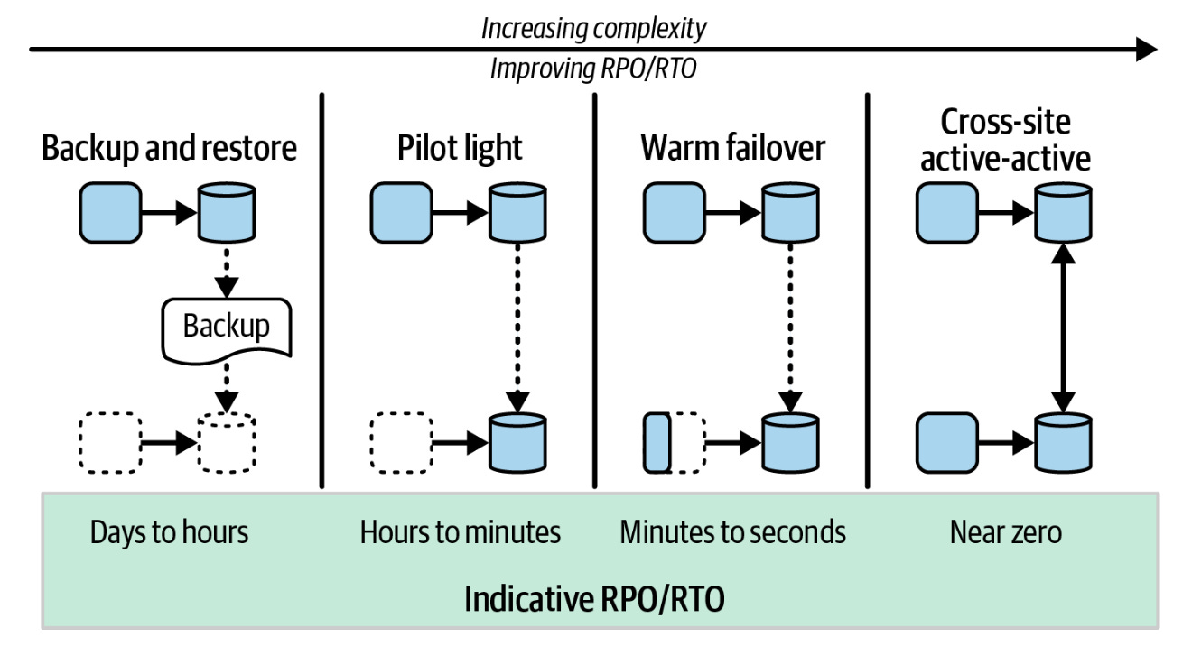
With the discussion of RPO and RTO in mind, let’s take a look at some common patterns used to implement DR in the wake of a major incident. In Figure 10-2, we can see an overview of each of the four patterns we will explore, arranged (broadly speaking) in order of increasing complexity and improving RTO and RPO.
If starting from scratch, many of these patterns can build on one another, allowing you to incrementally increase the complexity (and cost) of your DR solution over time. For example, a backup and restore approach requires rerouting, a pilot light setup will add the need for cross-site data replication and infrastructure automation, and a warm failover adds on the cost of having some infrastructure ready to go. So if you aren’t sure where to start, working your way through the patterns from left to right in Figure 10-2 makes a lot of sense.
If you have different RPO and RTOs for different parts of your system, you may also end up using a mix of these patterns. Note that they all require some form of rerouting of traffic, and most require some form of cross-site data replication. Those options are discussed later in this chapter.
Recovery by restoring data from a backup and loading it into a replacement system.
As outlined in Figure 10-3, with this pattern, data is periodically backed up to a separate site. In the event that the primary site fails, infrastructure needs to be provided at a new site, and the backed-up data restored.
This pattern is very straightforward to implement, consisting of a few steps:
1. Back up data regularly.
All data that you want to make available to the failover site needs to be regularly backed up, with the backup data stored somewhere other than the primary site.
2. Provision infrastructure on the failover site.
This would ideally be automated, as manual infrastructure provisioning would likely lead to longer RTO and an increased chance of errors.
3. Restore data from backup to the failover site.
Data is loaded from the backup location into the newly provisioned infrastructure.
4. Switch traffic from the primary to the failover site.
Once infrastructure is available and the data is restored, traffic can be switched to the secondary.
Ideally, your failover site runs the same core technology stack as the primary site, meaning that any investment in infrastructure automation on your primary can also be used on the failover (for example, being able to reuse Terraform scripts). Keeping the code to automate setup of the primary and the failover the same is very useful, as it means that you’ll have a higher degree of confidence that spinning up the infrastructure on the failover site will work. If your failover site uses a different technology stack—meaning it’s not possible to share automated infrastructure provisioning code between the primary and secondary sites—then it becomes even more vital that your DR failover process is regularly tested. A caveat to spinning up infrastructure on demand here comes in terms of guaranteeing that infrastructure is actually available when you need it, something we’ll explore later in this chapter.
This pattern is generally applicable in situations where your primary site is unavailable and you can tolerate a long RTO, and especially in those situations where you want to keep costs low. It’s important to note that regular tests of a backup and restore process are necessary to ensure that it actually works. One approach I’ve found useful is to perform a backup and restore to a secondary site as part of other regular activity (for example, a regular load test exercise).
The RPO of this pattern will depend on the frequency of backup. The RTO will be the longest of the patterns we’ll look at, and its time will depend primarily on how long it takes to restore data from the backup and provision replacement resources. With a fully automated process and smaller data volumes, this could be in the minutes to hours range. Manual recovery processes will likely extend these timelines greatly, as will the size of backups involved—terabytes of data take longer to send than gigabytes! Another major factor will be availability of the required computing resources. If you end up having to purchase replacement equipment, this pattern could easily result in a timeline of weeks or longer.
Data is constantly synced to a failover site, with infrastructure provisioned after failover.
With a pilot light setup, data is continually replicated from the primary to the failover site, as shown in Figure 10-4. Infrastructure is not provisioned until a failover is required, ensuring that costs can be kept down when working with public cloud infrastructure.
This pattern builds on a lot of the work done with a backup and restore, the main change being that the data is continually synchronized to the failover site. As such, the steps involved look fairly similar to the backup and restore pattern:
1. Replicate data continually.
As data is committed to the primary, it is continually replicated to the failover site. This can be done in a variety of ways, such as by making use of native database technology or application-level replication.
2. Provision infrastructure on the failover site.
The assumption is that databases and datastores are already present on the failover site, so only remaining resources like compute would need to be provisioned.
3. Switch traffic from the primary to the failover site.
Once infrastructure is available and the data is restored, traffic can be switched to the failover.
From an implementation point of view, the new source of complexity comes from the replication of data from the primary to the failover. For systems designed with this process in mind, it might be somewhat trivial to implement. However, things become more complex when adapting existing systems if you’re making use of a data product that doesn’t support this replication strategy natively. This is worthy of a more in-depth discussion later in this chapter, especially as the next two patterns also rely on this capability.
When compared to a backup and restore, the pilot light failover allows for a much shorter RPO because of more frequent data replication, while also reducing RTO by eliminating the time taken for data restoration.
The cost-saving of a pilot light failover really makes sense only in the context of the public cloud. Costs are reduced primarily in terms of not paying for infrastructure unless it’s used. But if your failover site is your own private infrastructure that you have to pay for regardless of whether it is used, then some form of a warm failover makes a lot more sense. At that point you’re already paying for the hardware, so you might as well use it.
Data is synced to a failover site, with at least some infrastructure already provisioned to handle traffic.
With a warm failover, as shown in Figure 10-5, data is continually replicated from the primary to the failover site, with at least some infrastructure already provisioned in advance of the failover itself.
Having some infrastructure provisioned even before the failover occurs results in a reduction in RTO for some functionality. How much infrastructure is provi…